Trigger Happy
At first, I tried to use the stop motion animation idea that my son inspired. With the machine moving the film slowly through the gate, it triggered the computer to capture each frame at the right time. The right time is when the shutter blade is not blocking the light (i.e. when the claw is not moving the film).
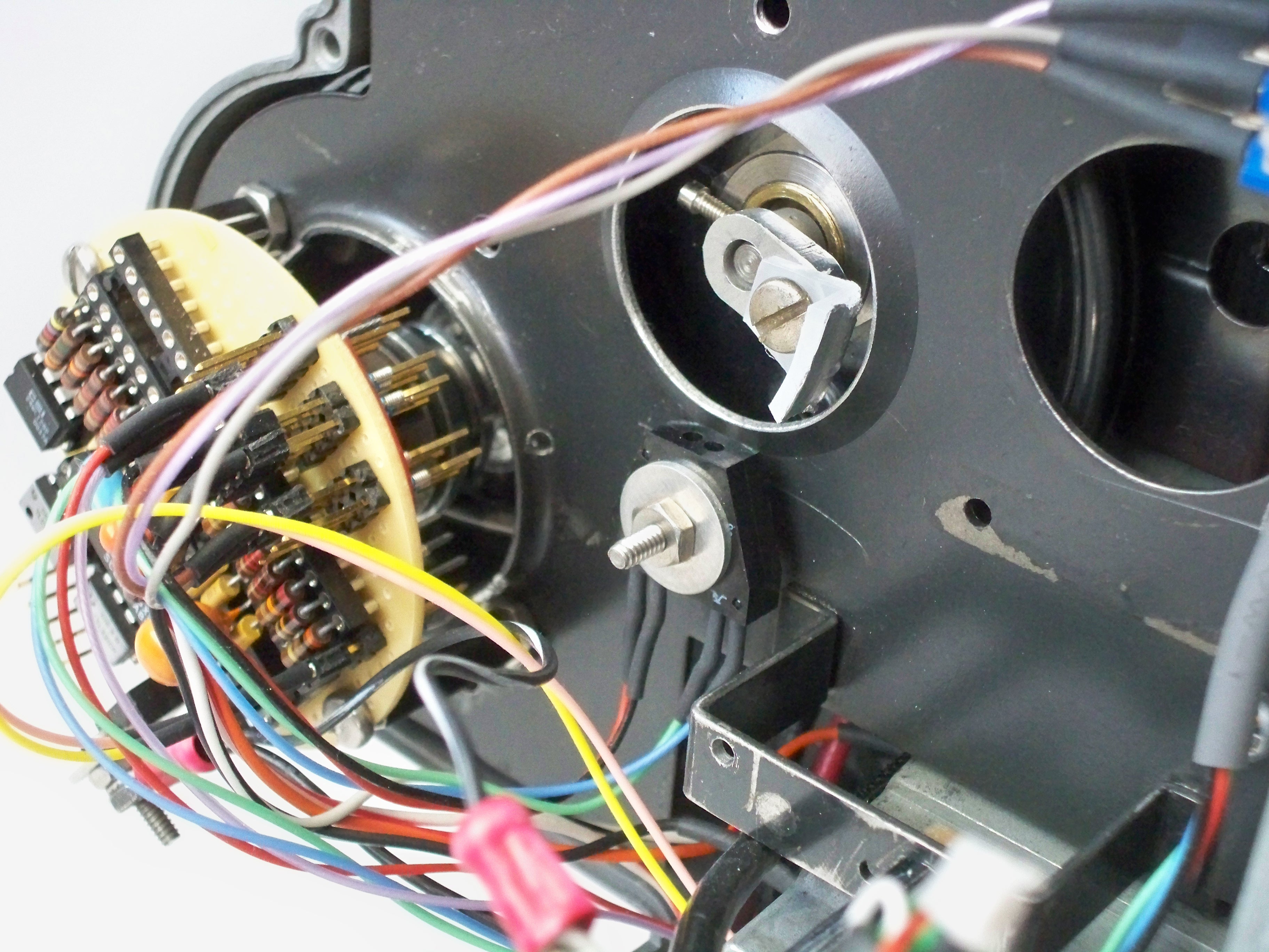
To detect the right time, I use an OBP709 “Reflective Object Sensor” which contains an IR LED and a photodarlington transistor. The reflective object is a plastic flag attached to the shutter wheel shaft. This picture shows the sensor and the reflective flag…
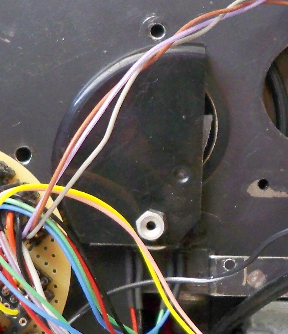
With the lamphouse cover off, daylight or room light can trigger the sensor, so I added a cover cut from a spray can cap…
For triggering the computer, typically a computer mouse is modified and the projector trigger connected to the left mouse button. Then the mouse pointer is positioned over the GRAB button on the computer and away we go! The down side is that you have to be careful not to move the mouse while capturing. I was using a freeware program called Stop Motion Animator which allows user defined hot keys for many functions, including frame capture. I set the software to trigger on the INSERT key, which doesn’t do much if the wrong program is on top. Instead of using a mouse, I bought a cheap USB numeric keypad…
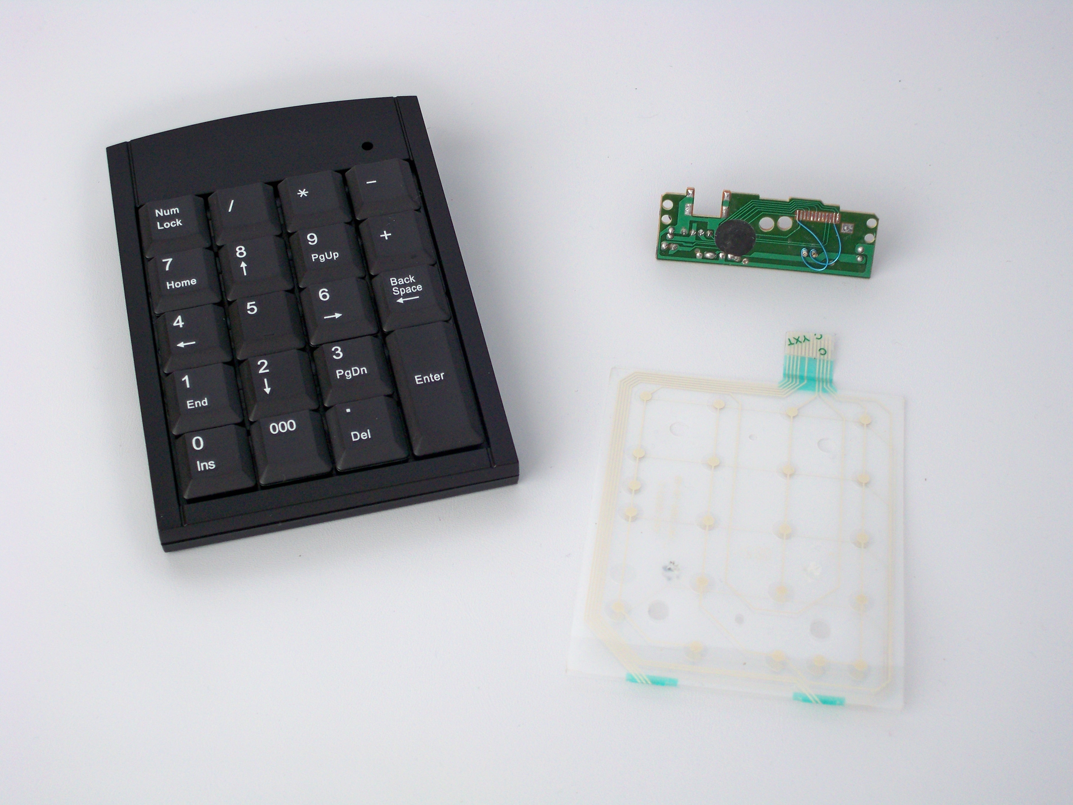
I discarded the case and the switch matrix and installed the little circuit board inside the projector. The sensor transistor is connected across the correct row and column pins to simulate the INSERT key. This scheme worked, but there was a big problem.
The Philips webcam makes good images only at 5 fps (more on that below). Using the stop motion approach with keyboard triggering, the trigger delay is not consistent and I could not capture reliably above 1 fps. This is too slow to sit and watch a 400 ft reel transfer, as is necessary for manual exposure adjustment to handle underexposed scenes.
So I abandoned the stop motion approach. I realized that at 5 fps, there is plenty of time in the cycle of the shutter wheel for the webcam to capture each frame. But the projector shutter must stay synchronized with the webcam. In the stop motion approach, the projector is the master and the software is the slave. I decided to make the camera the master, and sync the projector shutter to the camera capture rate.
This approach is a bit more complicated. The astronomers modify the Philips webcam to allow long exposures. I don’t need to alter the webcam’s operation, but I do need to detect when it is exposing. So I connected a wire to “pin 10” of the 16510 CCD driver chip (see Philips Webcam Teardown link). This signal controls the CCD substrate driver. When low, it resets the CCD pixels, erasing any charge from accumulated light. Normally, the webcam controller pulses it low during each video line transfer, but during exposure, it remains high, so it serves as a CCD shutter-open signal.

My motor controller uses a simple microcontroller to monitor the CCD substrate signal and the projector shutter sensor signal and continually adjust the motor PWM voltage so that the actual frame capture always occurs when the shutter is open. The controller actually monitors the delay from the end of exposure to the closing of the projector shutter. Since longer exposures start earlier, but the end point is constant relative to the video frame interval, the motor is synced to the end point. Also, if the shutter close time should encroach on the start of a long exposure, it is less disastrous than if it should overlap the end of a short exposure.
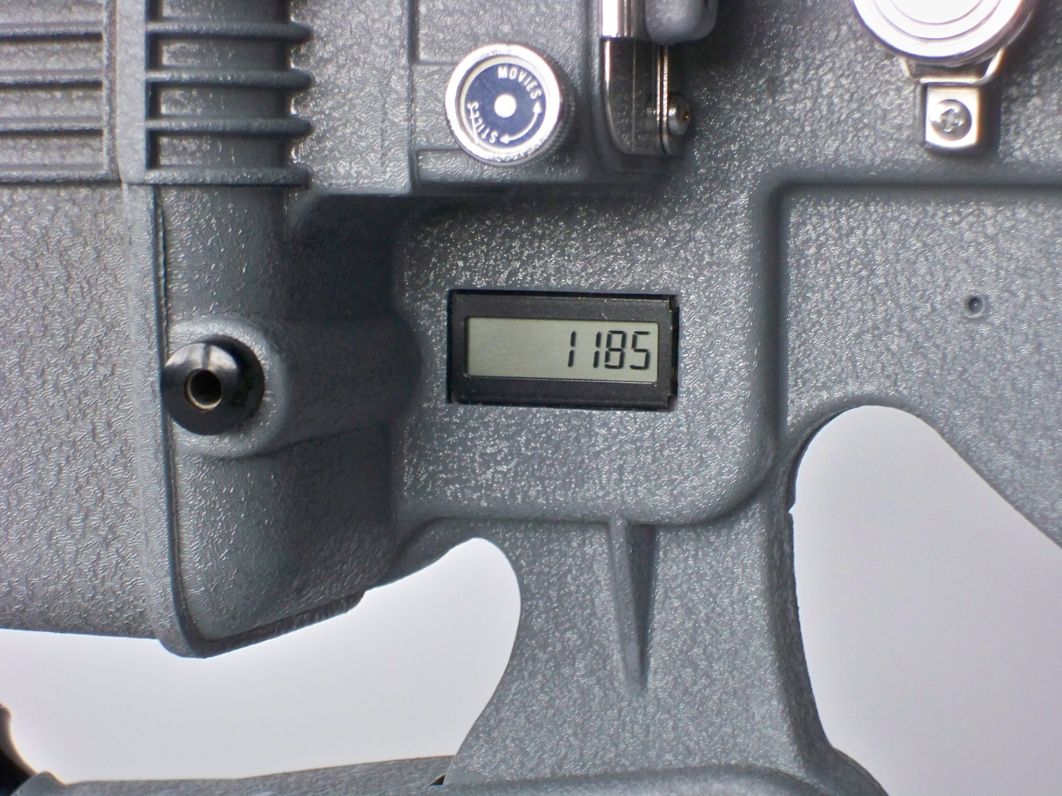
The projector shutter signal also drives a digital frame counter on the projector, so that I can verify that all the film frames actually make it to the captured movie file.