Computer
I doodled some circuits for synchronizing the projector shutter to the webcam. It’s not such a difficult problem, but I kept thinking of extra features to add, and the circuits soon reached the complexity level where a microcontroller made more sense. It’s much easier to add features and tweak values and logic in software than by rewiring circuits.
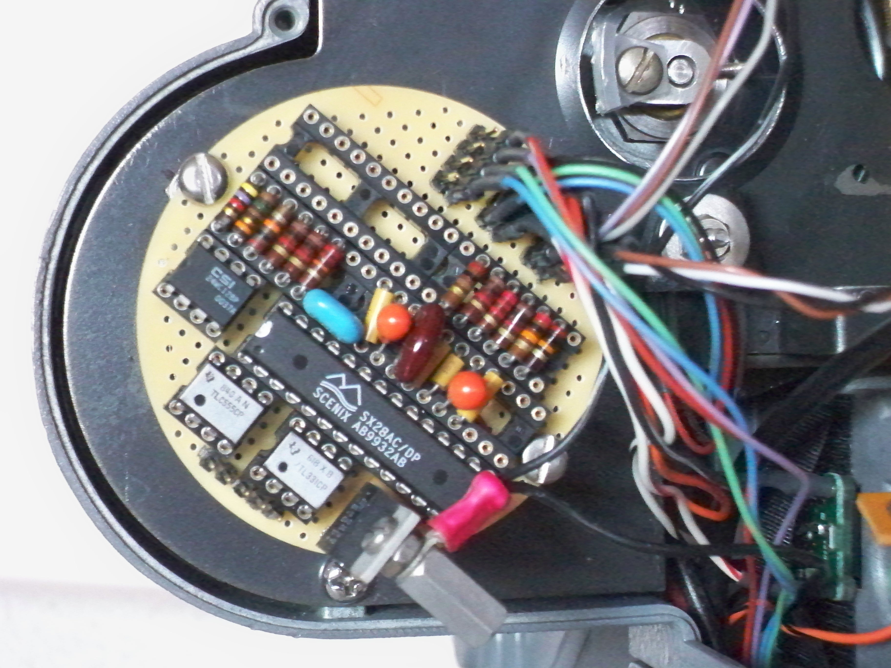
I had some Basic Stamp 2sx Interpreter chips on hand from a previous project. The controller function is not too demanding at 5 fps, so this slow but very easy to use microcomputer does the job perfectly. The micro and its interface components, including the PWM signal generator are built on a small round wire wrap board mounted where the projector blower used to be…
A toggle switch on the side of the projector sets the motor controller mode. The center position is OFF – the motor will not run. Down is MANUAL mode – the old projector speed control knob controls the speed from less than 1 to around 15 fps, useful for locating a starting frame, 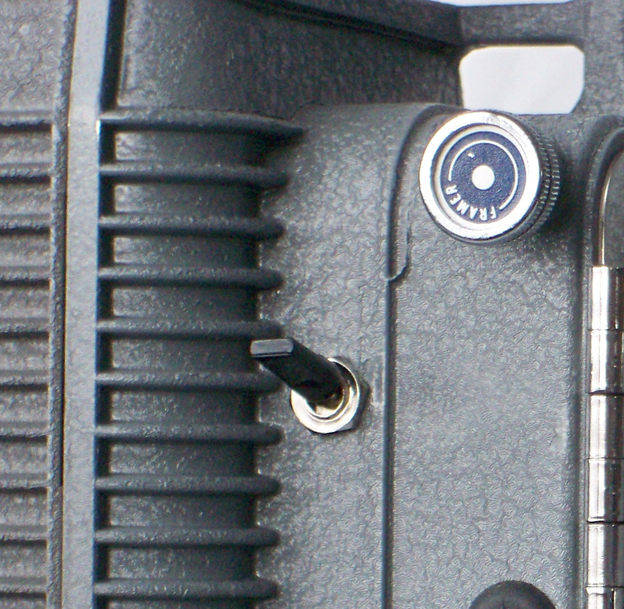 and for fast forward and rewinding the film. The speed control is now a 5K pot, connected directly to the micro, which then controls the PWM output. An added feature is that the projector shutter is always stopped in the open position.
When the toggle is up, SYNC mode is selected. Now the micro monitors both the shutter sensor and the CCD exposure signal. The shutter sensor flag is aligned so that the sensor output is low when the shutter is closed. That’s simple. But the CCD exposure is trickier. This signal is pulsing low all the time except during exposure. The Basic Stamp language includes a COUNT statement that counts pulses on an input pin for a specified time. At 5 fps, the webcam reads a line of the CCD every 400 usec, so I run COUNT for 800 usec, and if the result is zero, the CCD must be exposing.
The program loops continuously, alternately checking the CCD and shutter, and keeping track of when they change in terms of loop counts. Absolute time isn’t important, it’s only necessary that the exposure be timed relative to the shutter. When the shutter closes, the time is compared to the previous exposure time and a new PWM value determined for the next frame cycle.
I also connected the webcam LED signal to the micro. This allows the controller to start and stop the projector motor when the video recording is started and stopped on the computer. The shutter is in sync by the second frame cycle, so it’s not necessary to back up the film and get a running start.
The micro resets the frame counter at the start of each record, and when entering manual mode. A red/green status LED on the side of the projector flashes green during the delay from exposure to shutter, so it’s easy to keep an eye on the sync performance.
The Basic Stamp program is here…Project Files
Here’s the schematic of the whole machine (click to enlarge)…
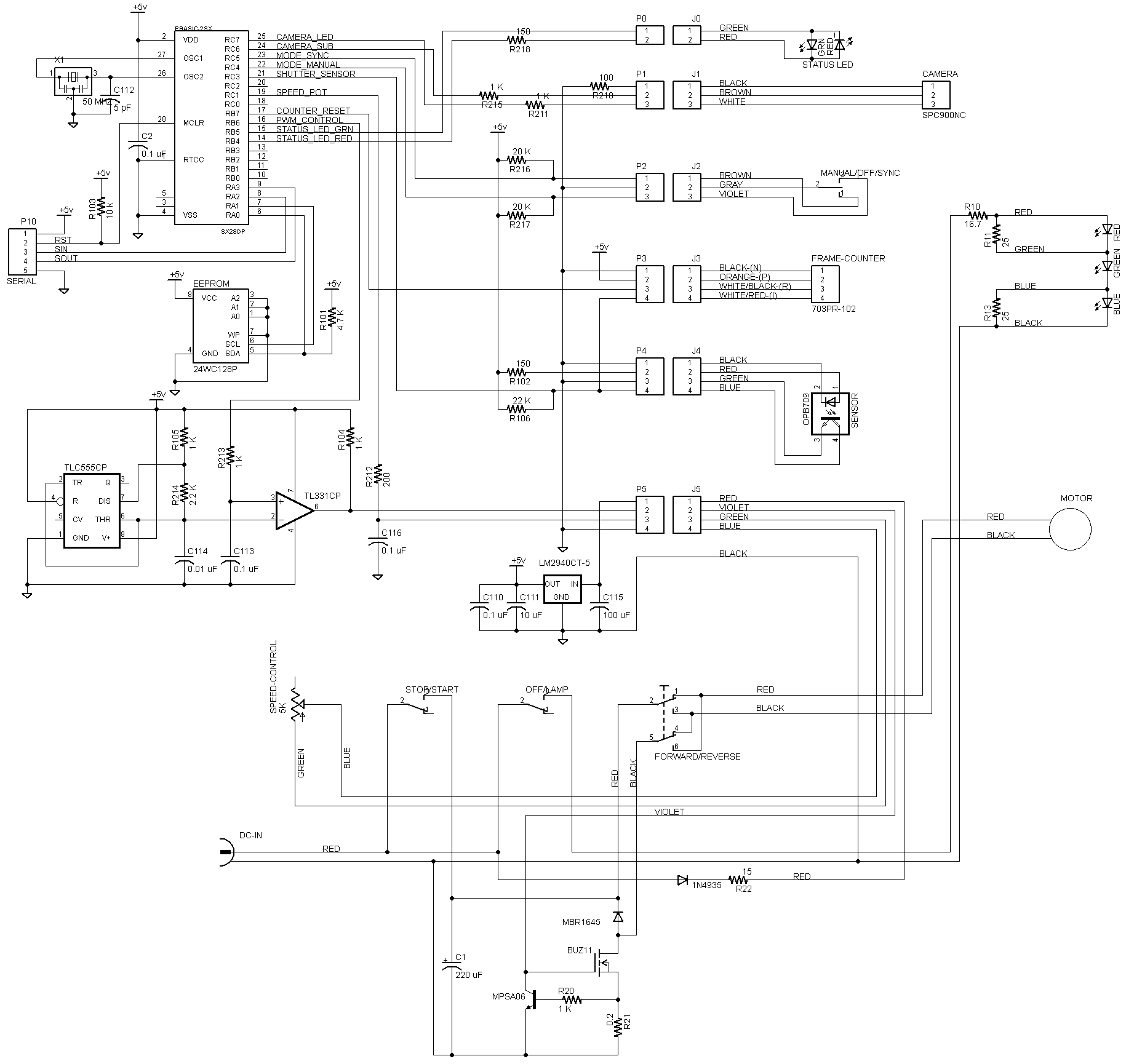
The Basic Stamp micro chip has an EEPROM attached to store the program and any data to be saved between runs. Most of the circuit just interfaces the other devices to the micro.
The motor PWM controller is the most complicated interface. The 555 is a sawtooth generator, free running at about 30 Khz (so it won’t produce an audible whine in the motor). The 331 comparator generates the PWM signal, with the pulse width controlled by the micro output PWM_CONTROL. The PWM signal drives the gate of the low-side FET switch. The FET circuit includes a current limiter that prevents overloading the 12V supply when the motor is starting or is suddenly reversed by flipping the direction switch at speed. Without the current limit, the supply sags and resets the micro. The DC supply is a cheap 12 volt, 5 amp AC adapter. The manual speed control pot doesn’t connect directly to the PWM generator. The micro reads its value in manual mode and passes it to the PWM directly.

hello Dan,
thanks for sharing all your work and knowledge. I’m currently working on a project using a Mark 610D projector, a Logitech 4000 PRO as web-cam, and an Arduino as controller. The Logitech is using a similar chip than the SPC900, so I was able to get the shutter signal. I also succeed to convert your Basic Stamp code to Arduino code. I had some difficulties to get a working speed regulation, but now it works fine.
I have now a problem with the link between your VB application and the controller. It seems that you are using the web-cam led signal for starting and stopping automatically the projector when the computer is recording the video. Can you confirm?
Can you give me more details on the led connection because on my web-cam, the led is continuously ON when the web-cam is connected by a software, I don’t see any effect of video recording.
Comment by Olivier CANUT — April 30, 2013 @ 5:11 pm
Yes, the LED line controls the motor.
The Philips webcam does not turn the LED on automatically when recording video. It must be turned on by the software. The DSwcOpen control provides access to the LED as a camera property.
If your webcam’s LED is on all the time, it may be controllable the same way – I don’t know. If it’s not accessible through DSwcOpen, you’ll have to use some other channel to get that signal from the VB program directly to the Arduino – probably via USB/Serial port. It doesn’t have to go through the webcam – that was just a convenient solution for me.
Comment by jimmymc — April 30, 2013 @ 5:46 pm