Bright White Light
The light source had to be bright, yet small and cool. LEDs are perfect for this job. I originally tried arrays of white LEDs in front of the projector lens, using the lens as a condenser. But the white LED spectrum is not ideal, and the light must be diffuse for best results, so the final design uses a single RGB LED device inside the lens mount with a diffuser and no condenser lens.
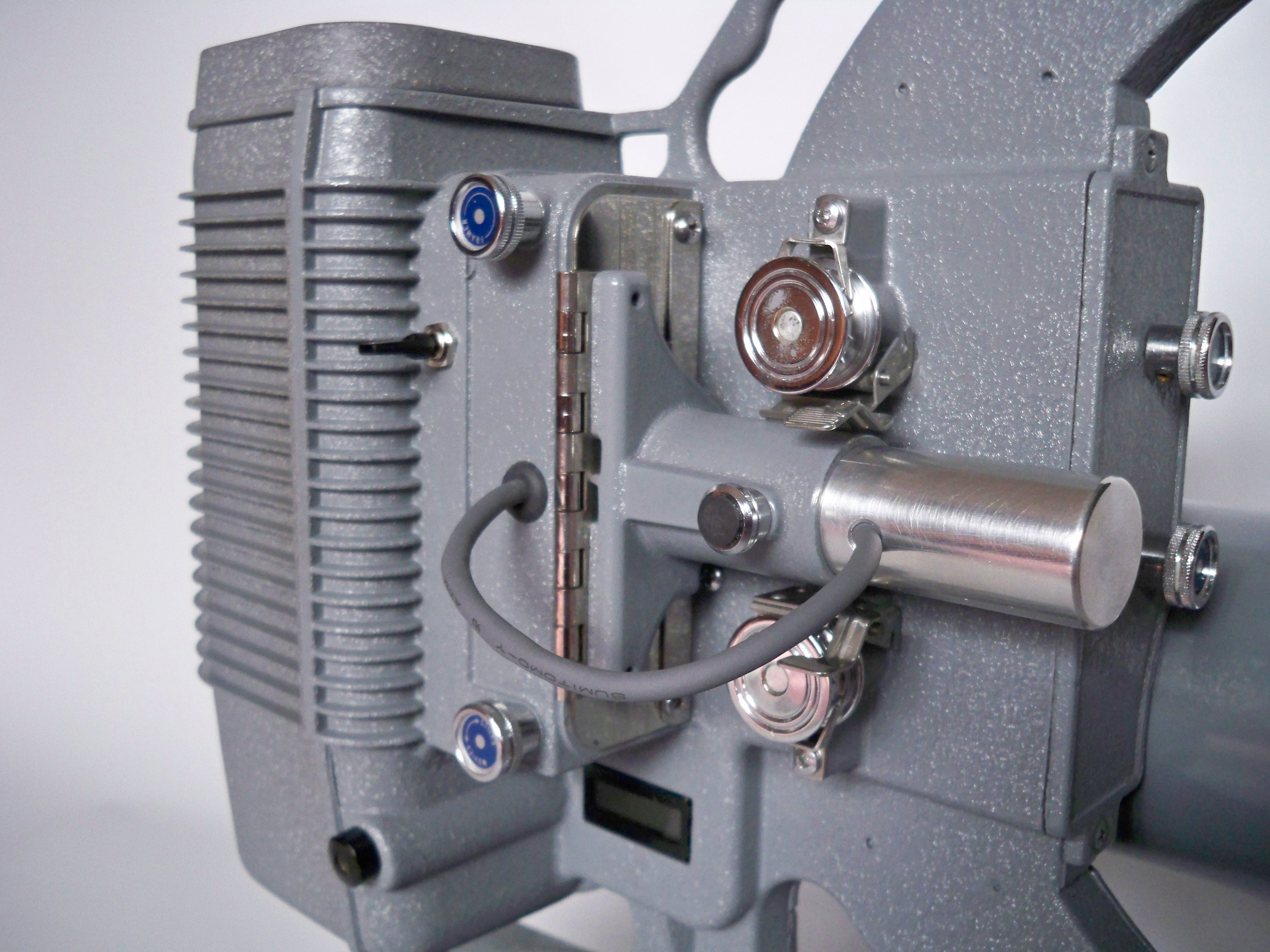
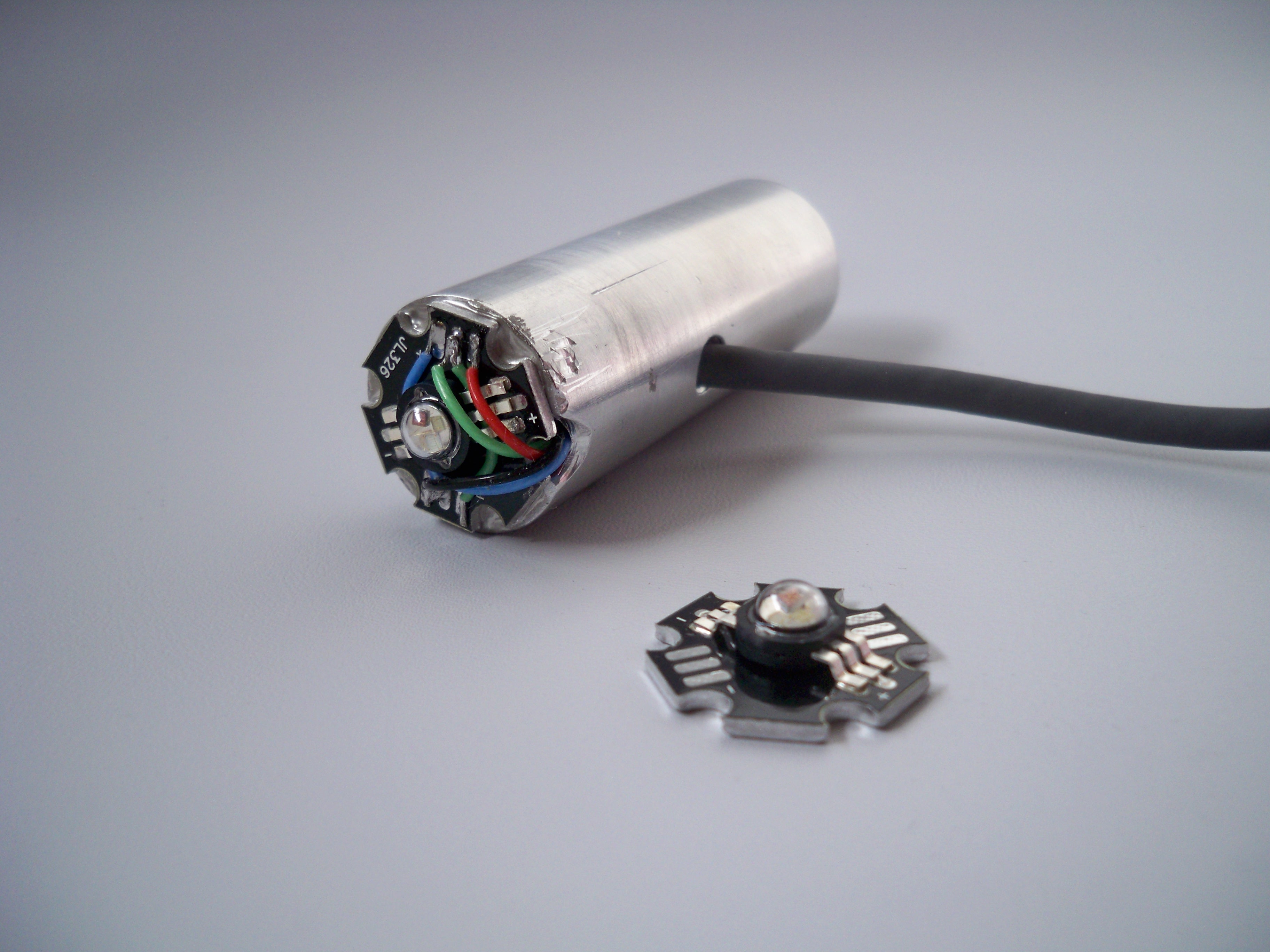 The LED is attached to a 7/8″ diameter aluminum bar using thermally conductive epoxy. The bar acts as a heat sink, dissipating the heat outside the lens mount. With RGB LEDs, the red LED brightness drops a lot more with increasing temperature than the green and blue LEDs. So to avoid a color balance shift during movie transfer, it’s important to keep the LED relatively cool and at a fairly constant temperature. The solution is a good heat sink, and warming the LEDs up for a few minutes before starting a transfer.
The LED wiring runs through a hole in the bar to emerge outside the lens mount. The LEDs are connected in series, with a single resistor to set the LED current, using the machine’s 12 volt power supply. The two tap points between the series LEDs are brought out so that the current in an individual LED can be trimmed by adding a parallel resistor. This allows the source to be matched to the response of the CCD, to maximize dynamic range (more on that below). I changed the camera to B&W raw mode using the WcRmac program, then adjusted resistor values until the bayer pattern in the image disappeared, so I know the LED is driving the 3 CCD colors equally. The resistors are mounted on a terminal strip in the bottom of the lamphouse…

I’ve thought about using the microcontroller to switch the LEDs on and off for each frame. Timing the on pulses separately would allow the micro to control color balance over a wide range without using trimming resistors. But the simpler approach is working for now.
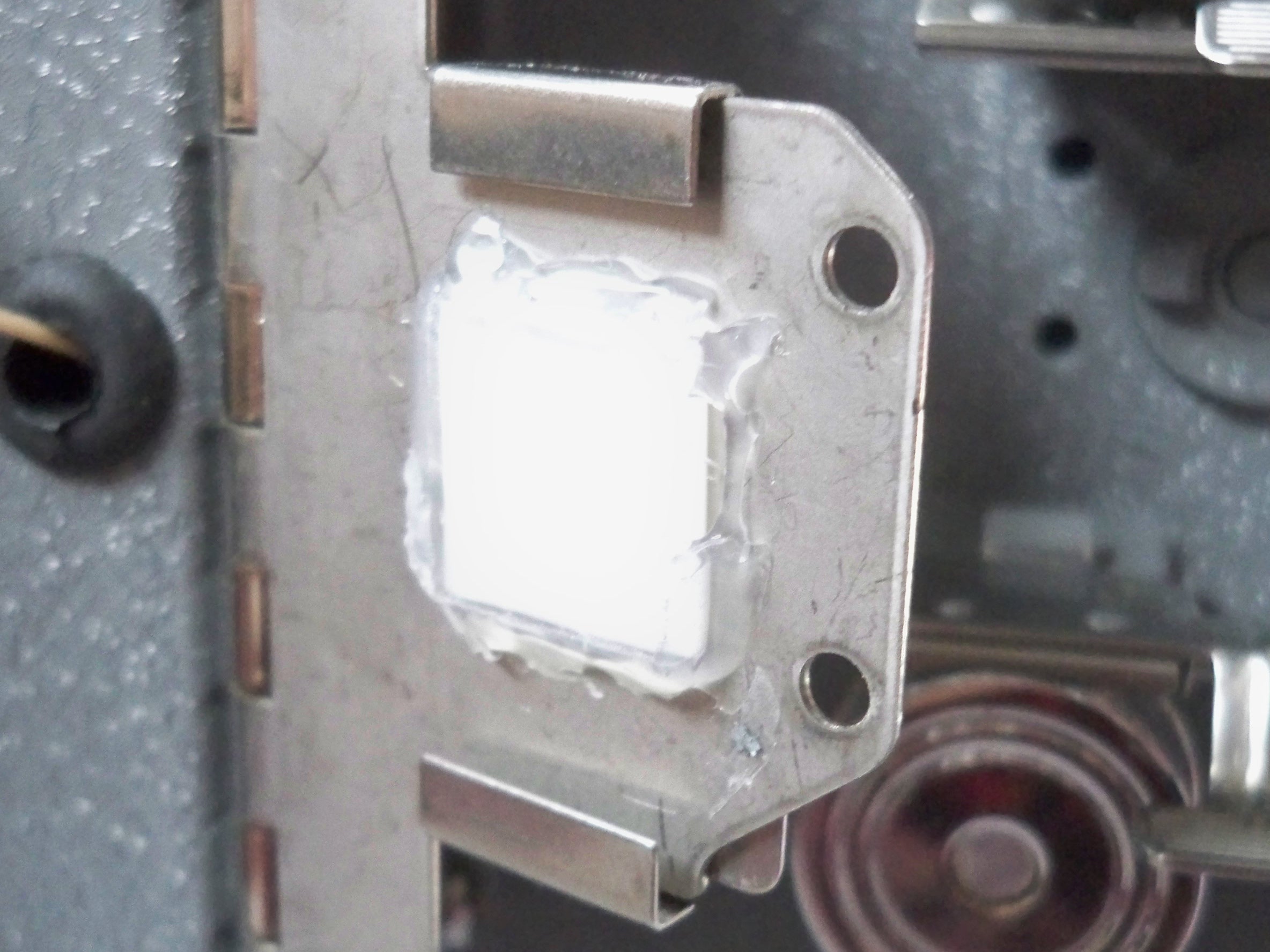
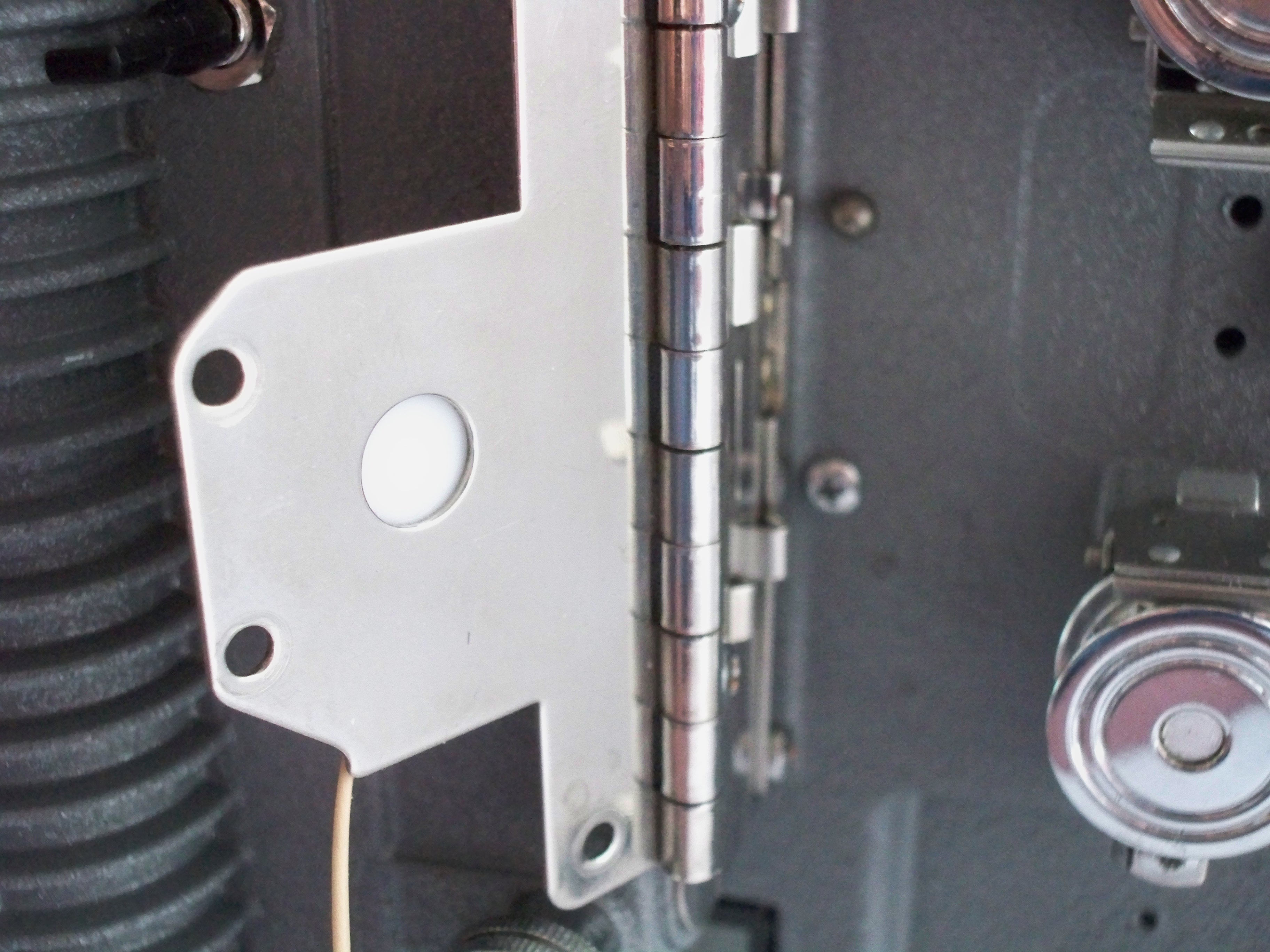
The diffuser is a small square of opal glass attached with hot glue to the lens mount plate. This location is within 2mm of the film plane, and it does a great job hiding scratches. Opal glass is clear glass with a layer of translucent white glass about 0.5mm thick on one side. The white side is toward the film. The closer the diffuser is to the film, the better it works, but it must be clean, polished and uniform in color, so it’s not visible, as it is in the focus range of the lens.

Hi Jim,
I am working on my own DIY telecine. I was wondering if you could tell me what kind of LED light source you used and where you got it.
In a nut shell, my telecine uses my daughter’s Canon 5D Mark II using the MP-E 65mm macro lens. I focus the lens directly on the film (from the lamp housing side) and take 1080P HD video. With a magnification of around x5, I can almost fill the 35mm sensor of the 5D with the 8mm film frame. I use ffmpeg to grab the HD video frames, creating a .ppm file per frame. I use my own software (that I just finished today) to sort out the duplicates. I plan on using AviSynth for post processing.
I noticed you have not blogged on the “God is Kind” portion of your web site for about a year. I guess you don’t add new material there any more.
Thanks for the help,
Dave
Comment by Dave Richards — April 23, 2011 @ 3:46 pm
Dave,
It’s a 3W (1W/color) Luxeon from FCB electronics. Search eBay for Luxeon RGB LED and you should find them.
Some RGB LEDs have a common connection for the 3 LEDs, so you can’t run them in series as I did. The LED I used has separate pins for all 3, so you can connect any way you like.
Good luck on your project. The 5D should give you superb images!
Jim
Comment by jimmymc — April 24, 2011 @ 7:36 am
I believe that if you were to use PWM to control the LED brightness you may create interference patterns due to the two rates, PWM vs. webcam scan rate.
Comment by Greg — November 11, 2016 @ 1:09 pm
The Sony ICX098QB in this webcam has a global electronic shutter, not a rolling shutter typical of CMOS sensors. All pixels integrate at the same time, so there wouldn’t be a problem with pulsing light.
Comment by jimmymc — November 11, 2016 @ 2:10 pm
“The two tap points between the series LEDs are brought out so that the current in an individual LED can be trimmed by adding a parallel resistor.”
But adjusting the current for one LED will affect the current going through the others, right? For example, if we trim the current in the first LED, the 2nd and 3rd (since they’re in series) will also be affected, right?
Comment by Greg — November 18, 2016 @ 8:49 pm
Yes, they will. The object is changing relative brightness of the LEDs, to balance the CCD output channels. Without the tap points, that would not be possible.
Comment by jimmymc — November 18, 2016 @ 10:16 pm