Retro Telecine

Building an 8mm Telecine Machine with Style

Saturday, January 31, 2009

Introduction

This is the story of a fun project. I needed to digitize my family’s collection of 8mm movies before it was too late. I chose to build a machine to do it, rather than pay someone else to do it. Since I also enjoy old photo equipment, I built the telecine machine using a projector from the 1950’s, almost identical to the one we used when I was a kid to show the movies that I am now scanning.100_0683.JPG

So this project is both practical and nostalgic. For less than $200, I have a high quality (see some sample frames) telecine machine that will save us about $2000 in copying service costs. At the same time, it’s been great fun to work with a fine old projector and make a stylish retro telecine machine out of it.

The photo here is of the complete machine. With no extra widgets bolted on like most telecine units, there are only a few hints that this is no ordinary movie projector.

WARNING:
My explanation might make the project seem pretty easy, but it has not been so. I’ve made a lot of changes as I encountered problems with my first ideas. If you try to do this, be prepared to be persistent! It’s not a trivial project, but it’s worth the effort when you finally see an old movie brighter and more beautiful than it ever appeared on the old vinyl screen. Did I mention the sample frames?


Friday, January 30, 2009

Movie Making

img_griswold.jpgA few months before I was born in 1958, my Dad started making 8mm movies. He took his new hobby seriously, learned good camera technique, and invested the time to edit what he shot. Dad built an editing desk in a cabinet in the corner of the family room. I remember many pleasant hours playing nearby and the sounds of the whirring gears as Dad cranked the spools back and forth, the clip of the scissors as he cut out scenes and tucked them in the neat, numbered holes of his plywood clip boards, the scrape and clank as he opened and closed the clamps of the splicer, and the smell of the acetone cement that held our memories together.

img_bolex.jpgThe product was a pair of films for each year, one of the big vacation trip, and one of the rest of our lives. The second always ended with Christmas. Dad would set up movie lights and tripod and we would have to come on stage on cue and act surprised at the pile of presents under the tree, even though we had already seen them, and in fact probably knew what was in them after covert operations under the bed and in the closet.

I was fascinated with the whole business. Though I never did much shooting (film and processing were pretty expensive for a kid in those days), I loved to fondle the cameras and lenses and pretend to be a real cinematographer.

img_dejur1000.jpgI was a real projectionist, and getting out the old DeJUR projector and watching movies was at the top of my list of fun things to do. The projector, like the cameras, had so many knobs and switches and involved proper procedures and adjustments to work smoothly and not damage the precious films. I can still smell that 1000 watt lamp and hot projector oil, and I can still hear the motor and the clicking of the claw in the sprocket holes. I have fond memories of enjoying our memories.

Dad continued to make movies until I was a teenager in the 70’s. In college, I began doing 35mm still photography, which led to a job at Eastman Kodak, where I met my wife, and also became a bit of a pioneer in digital cameras, and… well, Dad’s hobby has certainly left it’s impression.

Fortunately, we still have those old movies, and the film has not deteriorated noticeably… yet. Dad had a VHS tape made from the 1958 family movie a few years ago. It’s fun to watch it, but the picture looks so bad that we never had any more done. It’s just as well, since we’re in the DVD age now and copying the old movies digitally means they can be re-copied in the future without losing anything. But it’s still very expensive. It would cost around $2000 to do Dad’s whole collection and so we have procrastinated.

Recently, my son was trying some stop motion animation, making fun short films of lego men fighting epic battles on his desktop, using a little webcam. It occurred to me that the same process could digitize the old movies pretty easily. Google brought me some sites of others who had done that very thing with success, so I jumped in. This blog is the story of that project. Maybe it will give you some ideas or encouragement.


Thursday, January 29, 2009

Design

My machine is a frame-by-frame telecine. As the projector mechanism slowly advances the film, each frame is captured by a digital camera and added to a movie file on the computer hard drive. When all the frames of the movie have been captured, the file can be played on the computer, or burned to a DVD for normal TV viewing. Once a movie is converted to digital format, it can be duplicated many times with no loss of quality.

Home built telecines (and lower cost professional machines) are typically built on a standard movie projector as a convenient framework and film transport. In a projector, light passes from a lamp behind the film, through the film gate, through the lens and on to a screen far away. Telecine machines follow the same plan, except that they mount the camera not-too-far away from the front of the machine to capture the projected image.

The challenge of my design was to fit everything into the original projector “footprint” without compromising the image quality of the movies produced. I chose to reverse the usual light path, mounting the camera in the lamp-house behind the film, where there was plenty of room, and placing the illuminator in the projector lens mount in front of the film. So light passes from the LEDs inside the lens mount through the front of the film into the projector to the camera…

100_0602A2.JPG

There is a popular belief that the image is not as sharp when the emulsion side of the film is away from the lens. There’s no reason this would be true, and from what I’ve read, it is not. In fact, in movie theaters, the emulsion on the movie print is away from the lens because it’s a contact print made from a negative and when contact printing, the emulsion of original and dupe must be in contact. Anyway, I can’t see any difference.


Wednesday, January 28, 2009

Ebay

The first step was to obtain a projector. Most telecine DIY-ers seem to be using the well made and modern Eumig dual-8 projectors. Mom bought Dad one of these in the 70’s, but it never had the same emotional appeal for me as the classic DeJUR.

So it was natural for me to start with the one I loved. Dad only shot a little Super 8, so I was content to make a Regular-8mm-only telecine. The old DeJUR machines are readily available on Ebay, and I ordered this one…
img_ebay1.jpg
img_ebay2.jpg
img_ebay3.jpg
It’s an earlier model than the one Dad had, but I think the older base style matches the rest of the machine better. Industrial design is important!

img_ebay4.jpg
The Ebay seller wrapped some shredded newspaper around the projector, stuffed it loose into that neat old wooden case, and wrapped the latter with cardboard and packing tape.

The projector must have bounced around a lot, since it hammered the case to pieces in the mail, but happily, the projector and its 750 watt lamp were unscathed. It worked perfectly out of the box. And it smelled just the way I remembered.

100_0598.JPG
I took the machine apart, cleaned it all up, and set aside the parts I don’t need – mostly just the lamp, socket, heat shields and blower. My machine will be cool in more ways than one. Of course, without the heat, the old familiar smell is gone, too, so in a moment of weakness, I bought another DeJUR from Ebay.

img_ebay5.jpg
This one came with all the original accessories, including a full bottle of genuine DeJUR projector oil, and the wooden case arrived in perfect (old and worn) condition. Now I can enjoy the sounds and smells and compare the digital telecine viewing experience side by side with the way it used to be. And, of course, I now have spare parts for the telecine. Maybe I need help…


Tuesday, January 27, 2009

Transportation

I remember running our old DeJUR in “slow motion.” Turning down the speed knob, the motor’s whine would drop into a lower register and you could easily see each frame go by. But don’t try to go too slow or the motor will stall and a little heat shield screen will drop into the light path and the image will be very dark. Of course, that heat shutter might stick and then we see the thrilling spectacle of a hole melting in the film, projected larger than life on screen.

Well, for the telecine, I don’t have to worry about anything melting. But I do need to run the projector slowly, since the camera and computer can’t capture fast enough to move the film at 18 frames per second.

The original motor speed control was just a rheostat, which didn’t provide very good regulation. If anything binds, the motor will slow down a lot. I tried using a sold state “Router Speed Control” but the old motor is just too small and weak for the job. It could not run slowly enough without stalling.

The only solution was a new permanent magnet DC motor, which sadly compromised the retro styling of the machine…

100_0582A.JPG

… but it runs smoothly and quietly at low speeds, from less than 1 to about 15 frames/sec, without stalling. I replaced the old rheostat with a voltage controlled PWM speed control, using a 555 timer chip, a comparator, and a power FET. The PWM circuit board fits neatly inside the base. Without the old AC motor, and the 750 watt lamp, the whole machine can now be powered by a 12 volt/5 amp AC adapter, so there is no AC wiring in the base any more…

100_0684.JPG

… and everything on the neat old control panel still works as labeled …

100_0576.JPG

The motor drives the shutter wheel through a rubber belt. The only change here is the removal of two of the three shutter blades, to give the camera more time for each capture. The remaining blade still blocks the light during the film advance, so I can watch a movie live on the computer without blurring. The extra blades were there to make the on screen flicker less annoying by raising its frequency. I added a bit of lead solder to the shutter wheel to balance the single blade, so the machine doesn’t vibrate when running fast…

100_0616.JPG


Monday, January 26, 2009

Trigger Happy

At first, I tried to use the stop motion animation idea that my son inspired. With the machine moving the film slowly through the gate, it triggered the computer to capture each frame at the right time. The right time is when the shutter blade is not blocking the light (i.e. when the claw is not moving the film).

To detect the right time, I use an OBP709 “Reflective Object Sensor” which contains an IR LED and a photodarlington transistor. The reflective object is a plastic flag attached to the shutter wheel shaft. This picture shows the sensor and the reflective flag…

100_0702.JPG

With the lamphouse cover off, daylight or room light can trigger the sensor, so I added a cover cut from a spray can cap…

100_0705A.JPG

For triggering the computer, typically a computer mouse is modified and the projector trigger connected to the left mouse button. Then the mouse pointer is positioned over the GRAB button on the computer and away we go! The down side is that you have to be careful not to move the mouse while capturing. I was using a freeware program called Stop Motion Animator which allows user defined hot keys for many functions, including frame capture. I set the software to trigger on the INSERT key, which doesn’t do much if the wrong program is on top. Instead of using a mouse, I bought a cheap USB numeric keypad…

100_0614.JPG

I discarded the case and the switch matrix and installed the little circuit board inside the projector. The sensor transistor is connected across the correct row and column pins to simulate the INSERT key. This scheme worked, but there was a big problem.

The Philips webcam makes good images only at 5 fps (more on that below). Using the stop motion approach with keyboard triggering, the trigger delay is not consistent and I could not capture reliably above 1 fps. This is too slow to sit and watch a 400 ft reel transfer, as is necessary for manual exposure adjustment to handle underexposed scenes.

So I abandoned the stop motion approach. I realized that at 5 fps, there is plenty of time in the cycle of the shutter wheel for the webcam to capture each frame. But the projector shutter must stay synchronized with the webcam. In the stop motion approach, the projector is the master and the software is the slave. I decided to make the camera the master, and sync the projector shutter to the camera capture rate.

This approach is a bit more complicated. The astronomers modify the Philips webcam to allow long exposures. I don’t need to alter the webcam’s operation, but I do need to detect when it is exposing. So I connected a wire to “pin 10” of the 16510 CCD driver chip (see Philips Webcam Teardown link). This signal controls the CCD substrate driver. When low, it resets the CCD pixels, erasing any charge from accumulated light. Normally, the webcam controller pulses it low during each video line transfer, but during exposure, it remains high, so it serves as a CCD shutter-open signal.

dwg_timing.png

My motor controller uses a simple microcontroller to monitor the CCD substrate signal and the projector shutter sensor signal and continually adjust the motor PWM voltage so that the actual frame capture always occurs when the shutter is open. The controller actually monitors the delay from the end of exposure to the closing of the projector shutter. Since longer exposures start earlier, but the end point is constant relative to the video frame interval, the motor is synced to the end point. Also, if the shutter close time should encroach on the start of a long exposure, it is less disastrous than if it should overlap the end of a short exposure.

The projector shutter signal also drives a digital frame counter on the projector, so that I can verify that all the film frames actually make it to the captured movie file.

100_0577.JPG


Sunday, January 25, 2009

Computer

I doodled some circuits for synchronizing the projector shutter to the webcam. It’s not such a difficult problem, but I kept thinking of extra features to add, and the circuits soon reached the complexity level where a microcontroller made more sense. It’s much easier to add features and tweak values and logic in software than by rewiring circuits.

I had some Basic Stamp 2sx Interpreter chips on hand from a previous project. The controller function is not too demanding at 5 fps, so this slow but very easy to use microcomputer does the job perfectly. The micro and its interface components, including the PWM signal generator are built on a small round wire wrap board mounted where the projector blower used to be…

100_0679.JPG

A toggle switch on the side of the projector sets the motor controller mode. The center position is OFF – the motor will not run. Down is MANUAL mode – the old projector speed control knob controls the speed from less than 1 to around 15 fps, useful for locating a starting frame, 100_0578A.JPGand for fast forward and rewinding the film. The speed control is now a 5K pot, connected directly to the micro, which then controls the PWM output. An added feature is that the projector shutter is always stopped in the open position.

When the toggle is up, SYNC mode is selected. Now the micro monitors both the shutter sensor and the CCD exposure signal. The shutter sensor flag is aligned so that the sensor output is low when the shutter is closed. That’s simple. But the CCD exposure is trickier. This signal is pulsing low all the time except during exposure. The Basic Stamp language includes a COUNT statement that counts pulses on an input pin for a specified time. At 5 fps, the webcam reads a line of the CCD every 400 usec, so I run COUNT for 800 usec, and if the result is zero, the CCD must be exposing.

The program loops continuously, alternately checking the CCD and shutter, and keeping track of when they change in terms of loop counts. Absolute time isn’t important, it’s only necessary that the exposure be timed relative to the shutter. When the shutter closes, the time is compared to the previous exposure time and a new PWM value determined for the next frame cycle.

I also connected the webcam LED signal to the micro. This allows the controller to start and stop the projector motor when the video recording is started and stopped on the computer. The shutter is in sync by the second frame cycle, so it’s not necessary to back up the film and get a running start.

The micro resets the frame counter at the start of each record, and when entering manual mode. A red/green status LED on the side of the projector flashes green during the delay from exposure to shutter, so it’s easy to keep an eye on the sync performance.

The Basic Stamp program is here…Project Files

Here’s the schematic of the whole machine (click to enlarge)…

dwg_schematic.png

The Basic Stamp micro chip has an EEPROM attached to store the program and any data to be saved between runs. Most of the circuit just interfaces the other devices to the micro.

The motor PWM controller is the most complicated interface. The 555 is a sawtooth generator, free running at about 30 Khz (so it won’t produce an audible whine in the motor). The 331 comparator generates the PWM signal, with the pulse width controlled by the micro output PWM_CONTROL. The PWM signal drives the gate of the low-side FET switch. The FET circuit includes a current limiter that prevents overloading the 12V supply when the motor is starting or is suddenly reversed by flipping the direction switch at speed. Without the current limit, the supply sags and resets the micro. The DC supply is a cheap 12 volt, 5 amp AC adapter. The manual speed control pot doesn’t connect directly to the PWM generator. The micro reads its value in manual mode and passes it to the PWM directly.


Sunday, January 25, 2009

Webcams

A lot of scientific and industrial equipment uses small video and digital cameras to look at things so a computer can analyze or measure something. These are called machine vision cameras, and they are sometimes nothing more than good quality cameras without viewfinders and other human conveniences. These cameras are commonly used in telecines as well, but they are expensive – the cheapest ones start at around $300 and they go up quickly into the $1000’s.

Webcams are the poor man’s machine vision cameras. They are small and simple, yet include a computer interface (usually USB) and have lots of software support. It’s fair to say that the major challenge of this project has been to squeeze the most out of a very cheap camera!

I started with a Logitech Quickcam Communicate Deluxe. It has a 1.3 MP CMOS imager that provides very nice images when used as a live video or snapshot camera (e.g. when used as a webcam). But the CMOS imager is a little short on dynamic range for film scanning (see Dynamic Range article below). The CMOS image sensor is noisy, and the Logitech processing includes a denoising algorithm that mangles the detail in the shadows.

img_logitech.jpgSo I did some more searching and found the Philips SPC900NC webcam. It’s a discontinued model, but it has a Sony CCD in it, and is very popular with amateur astronomers so there is a lot of info on the web about modifying it. This camera produced a noticeably better image than the Logitech. There is still noise in the shadows, but it’s very random and the image doesn’t display the artifacts of aggressive noise processing. The camera has a bit more dynamic range (probably actually 1 bit more), and provides a gamma adjustment that is very helpful for telecine. These cameras are still sometimes available on Amazon and Ebay – mine was only $30. The earlier Philips ToUCam Pro 740, 750 and 840 used the same CCD and processor chip and are a suitable substitute.

To get a significant improvement in image quality would require a higher res machine camera which would cost about $600, so the cost of the machine would quadruple, but it might be worth it. There is room in the lamphouse for a little bigger camera, so it’s a possibility.

Here are samples from the two webcams I tried. The top image is from the Logitech, captured at its full 1280×960 resolution. The bottom image is from the Philips, also captured at its full resolution of 640×480. Click on the images to see them full size. The higher pixel resolution of the Logitech does not make up for its faults.

frm_logitech.jpg
frm_philips.jpg
Here I adjusted the levels so you can see the shadow detail. Again, the Logitech sample is on top. It’s easy to see here that the lower resolution Sony CCD actually preserves more detail than the higher res CMOS imager. The CCD noise is random and resembles the grain of the film, so it looks better than the noise cleaning artifacts of the CMOS imager. Of course, the best of both worlds would be a 1280×960 CCD!

frm_logitechdetail.jpg
frm_philipsdetail.jpg

Like most webcams, the Philips offers a range of frame rates, from 5fps to 60fps. But these rates are not all created equal. The camera has only a USB1.1 interface, not the much faster USB2, so the data rate is pretty limited for streaming video. Above 5fps, the frames are compressed with increasing harm as the rate is increased. At 10fps and 15fps, the image shows severe 4×4 blocking, apparently from subsamping the color channels. At 20fps and higher, it looks like the camera only transmits a 320×240 image and the Windows driver upsamples to deliver 640×480 resolution, but the image is naturally very soft. So I am limited to 5fps to get good telecine quality.

Fortunately, with frame by frame transfer, the speed doesn’t matter. The playback speed is determined by the frame rate set in the AVI file, not the rate at which the capture is done, so the only penalty for slow running is that it takes longer to do the transfer. At 5 fps, a 400 foot reel takes about an hour and 45 minutes. That’s not too long to sit an watch, and of course, the scan is only done once per movie. But this is another reason why a machine vision camera is superior. Using a Firewire interface camera, it’s possible to run the movie faster than the normal 18fps viewing speed and still get high quality frame by frame transfers.


Saturday, January 24, 2009

Optics

To fit the camera inside the projector lamphouse, it has to be pretty close to the film. That means a short focal length lens – the typical 50mm enlarger lens won’t work. On the other hand, the lens can’t be too close to the film, or it will run into the shutter and claw.

dwg_baltar.jpgI happened to have an old lens of the ideal focal length. It’s a Bausch & Lomb Baltar 17.5mm f2.3. It was a state-of-the-art 16mm movie camera lens in 1946, and it’s design is excellent for this job. It has an adjustable aperture, and as is typical, it seems to give the best results at a mid range aperture of f4 or f5.6.

dwg_8mmfilm.jpgThe 8mm film frame has a diagonal of about 5.5mm. The CCD in the camera has a diagonal of 4.5mm. So the magnification required is about 0.8x. At magnifications this close to 1, the distance from the film plane to the CCD focal plane is roughly 4x the lens focal length, or 70mm. This makes a very compact camera unit …

100_0698.JPG
100_0699.JPG

… that fits nicely in the lamphouse of the projector …

100_0692.JPG

The lens and camera are mounted on a brass plate that slides over two standoff posts attached to the projector lamp mounting plate. Springs over the posts press the camera plate against two thumbscrews mounted above and below the camera, in a bridge plate fixed to the ends of the posts. Turning these screws together adjusts focus. Individually, they tilt the camera plate slightly, aiming the camera and lens up or down to easily align the camera field with the film frame vertically. A third thumbscrew in a block on the back of the bridge plate moves a standoff post attached to the camera plate to tilt it from side to side and thus adjust horizontal framing.

100_0689.JPG

The lens is mounted on a focusing helicoid, but at magnifications near 1, moving the lens mostly changes magnification, without changing focus very much. So I adjust the mag first, by turning the lens mount, then adjust focus and framing with the camera screws. Setup is quick and easy, and it’s much simpler and easier to construct than X/Y/Z translation mechanisms.

There are five springs altogether – the two post springs, a spring that holds the camera plate tilt post against the horizontal tilt screw, and two more that force the plate sideways against the main posts…

100_0694.JPG

The springs, screws and posts perfectly constrain the position of the plate, so it cannot shift if the projector is bumped.

100_0691.JPG

100_0693.JPG

I captured the image below just to confirm that the lens is sharp enough to not limit the resolution of the movie captures. Lacking a micro resolution target, I used a PROM chip, 3.5mm square, which provides plenty of fine lines. It’s captured with the webcam and lens at the same magnification I need for the telecine. The blue and orange colored bands in the middle of the chip are the result of the fine pattern aliasing on the color filter array of the CCD. This is the sign that the lens resolution is more than adequate. Grainy 8mm film doesn’t have such fine line patterns, so we won’t see aliasing in movie frames.

img_eprom.jpg


Friday, January 23, 2009

Open the Gate

I love the film gate on the DeJUR. It’s long and complicated, made of brightly polished stainless steel, and it does a great job keeping the film flat and in the right place without scratching it. In normal projection, the outline of what you see on the screen is determined by the little rectangular hole in the plate. It produces a blurry image edge with rounded corners. It also keeps you from seeing the sprocket holes go by.

100_0579.JPG

In a telecine, the image produced is a digital file and the edges are determined by the array of pixels on the CCD. We don’t want to capture the fuzzy hole in the film gate, but we do want to capture as much of the film frame as possible. So the hole in the gate must be enlarged. This job calls for careful filing away of the metal until the hole is big enough that you can see all four sides of the film frame through it, along with a bit of sprocket hole. The edges of the enlarged hole are rounded and the whole thing polished on a wheel and cleaned.

This gate design allows the film to be loaded or unloaded in mid-reel, by popping the lens mount open – pretty handy for telecine work.

100_0580.JPG


Thursday, January 22, 2009

Bright White Light

The light source had to be bright, yet small and cool. LEDs are perfect for this job. I originally tried arrays of white LEDs in front of the projector lens, using the lens as a condenser. But the white LED spectrum is not ideal, and the light must be diffuse for best results, so the final design uses a single RGB LED device inside the lens mount with a diffuser and no condenser lens.

100_0652.JPG

100_0643.JPGThe LED is attached to a 7/8″ diameter aluminum bar using thermally conductive epoxy. The bar acts as a heat sink, dissipating the heat outside the lens mount. With RGB LEDs, the red LED brightness drops a lot more with increasing temperature than the green and blue LEDs. So to avoid a color balance shift during movie transfer, it’s important to keep the LED relatively cool and at a fairly constant temperature. The solution is a good heat sink, and warming the LEDs up for a few minutes before starting a transfer.

The LED wiring runs through a hole in the bar to emerge outside the lens mount. The LEDs are connected in series, with a single resistor to set the LED current, using the machine’s 12 volt power supply. The two tap points between the series LEDs are brought out so that the current in an individual LED can be trimmed by adding a parallel resistor. This allows the source to be matched to the response of the CCD, to maximize dynamic range (more on that below). I changed the camera to B&W raw mode using the WcRmac program, then adjusted resistor values until the bayer pattern in the image disappeared, so I know the LED is driving the 3 CCD colors equally. The resistors are mounted on a terminal strip in the bottom of the lamphouse…

100_0704.JPG

I’ve thought about using the microcontroller to switch the LEDs on and off for each frame. Timing the on pulses separately would allow the micro to control color balance over a wide range without using trimming resistors. But the simpler approach is working for now.

100E0646.JPG100_0649.JPG

The diffuser is a small square of opal glass attached with hot glue to the lens mount plate. This location is within 2mm of the film plane, and it does a great job hiding scratches. Opal glass is clear glass with a layer of translucent white glass about 0.5mm thick on one side. The white side is toward the film. The closer the diffuser is to the film, the better it works, but it must be clean, polished and uniform in color, so it’s not visible, as it is in the focus range of the lens.


Thursday, January 22, 2009

Software

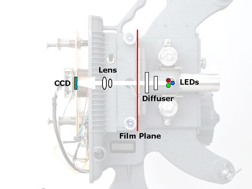
A lot of the magic of the telecine process is in the software. Frugality drove me to evaluate a lot of freeware programs to find the best tools without spending any money on software. Fortunately, there is a lot to choose from and I’ve put together a superb suite of software without spending a dime. Maybe my suggestions will save you spending all the hours I invested!

Initially, I used the freeware Stop Motion Animator program. It’s a simple tool to count captured frames and automatically assemble them into an AVI file. The programmable hotkey feature allowed me to use the keypad trigger described above.

But now I capture the movie continuosly, so I need a video capture program, not a frame capture program. There are many choices – I started by using VirtualDub (see below) in combination with a freeware tool called WcCtrl, developed for astronomical photography. WcCtrl allows camera settings to be adjusted during capture, displays numeric values for the settings, and allows multiple setups to be saved and reloaded.

This combination worked, but it was too awkward switching between the two apps, to start and stop and make adjustments as the movie scenes change. So I wrote my own capture app in Visual Basic, a task made easier by two wonderful freeware components… ezVidCap is a camera capture control object, and DSwcOpen is a camera control object (from the same author as WcCtrl). Both drop easily into a VB program and do all the hard work of accessing the camera, controlling captures and video file creation. That left me free to focus on workflow details and convenience of tweaking image adjustments during a transfer. The Visual Basic code for the app may be downloaded here… Project Files.

scr_telecineapp.jpg

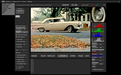
Some features of my capture app…

– Covers all the blue Windows junk on the screen. (When you adjust white balance with a lot of blue near the image, the balance comes out pretty blue!)

– App panel and controls are dark gray around the preview image, so it looks more like the movie will look on a flat screen TV. A slider allows all the controls to be dimmed for comfortable viewing of the movie.

– Controls to start AVI capture or film transport or both in sync.

– Automatically stops the transfer when the scene exposure changes more than an adjustable threshold. When the machine stops, adjust exposure settings and go again. The first and last 2 or 3 frames of the clip are easily deleted in post edit.

– Auto exposure process adjusts shutter time, gain and gamma to make best use of the dynamic range. The algorithm captures at each shutter setting, evaluates the histogram, chooses the best compromise between clipping at the high and low ends, then does the same process with gain. Finally, if there is still room at the low end, the gamma is turned down to move the bottom of the histogram down. Optionally restarts the transfer automatically when AE is complete, for unattended operation.

– Auto increments file number. Sets of files with sequential numbers are auto-merged in VirtualDub during post edit.

– Displays RGB and luma histograms of the image during transfer. Histograms make it a lot easier to fine tune the exposure settings.

– Magnifier displays a 4X portion of the image, for easy focusing.

– All camera settings are controlled by sliders on the main window. Settings can be adjusted over the full range or over a preset restricted range. Profiles of settings can be created, named and saved.

– Built in AVI player for instant replay of captured clips.

– Easy frame grab and save from either capture preview or playback modes.

I use the HuffYuv codec during capture. This codec uses lossless Huffman compression of the YUV video data from the webcam, so the captured files require about half the hard disk space of uncompressed data, but there is no image quality loss. It’s vital to avoid any lossy compression until all post processing is done.

Another interesting tool by the author of WcCtrl and DSwcOpen is WcRmac. This tool can reprogram the EEPROM in the Philips camera, to put it into raw capture mode, or to change default settings. The program will also display all the parameters set for the image process chain. I tried the raw mode, but didn’t get too far with that.

After the transfer, I edit the video file to remove splice frames and the few bad frames created when the transfer was stopped and restarted to make image adjustments. I use VirtualDub, a freeware video capture and edit program that is loaded with capabilities. This program handles huge AVI files quickly. It uses plugin filters to process the video, but the more powerful tool for that job is AVISynth, which works with VirtualDub to apply processing defined by a script to the video data before VirtualDub displays or saves it.

scr_virtualdub.jpg

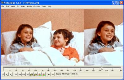
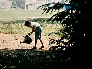
The post processing in AVISynth removes grain, noise, dirt spots and camera shake, then adjusts levels and sharpens. The resulting video looks better than the original film. Fred Van de Putte is the expert in this work – see his wonderful sample video here… Fred’s AviSynth comparison. I started with Fred’s AVISynth script and I’m experimenting with tuning it for the images I get with my system. The resulting video is amazing on a good LCD television! Here’s a before and after comparison clip from my machine…

ERROR: FLV player could not be loaded.

I made up a test loop of various scenes to evaluate process settings…

ERROR: FLV player could not be loaded.

My script is here… Project Files.

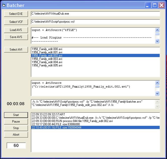
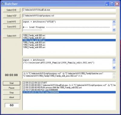
VirtualDub crashes sometimes, after processing a lot of AVI data, so I break up the edited AVI into segments of 1000 frames each and post process them one at a time. To save time and typos running the multi file process, I wrote a simple Visual Basic app called Batcher to create the AviSynth scripts and command lines for VirtualDub. Batcher launches VirtualDub for each segment, then watches for it to finish, or for the output file to stop growing. Batcher then terminates VirtualDub if it is hung, and starts it fresh for the next segment. The whole 3 to 4 hour process runs unattended, in spite of the glitches!

scr_batcher.jpg

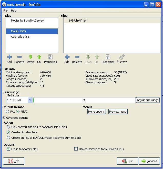
I am archiving the edited AVI files for each film on two hard drives, but for distribution to my family, DVDs are a must. There are a lot of programs to create DVDs, and I tested a bunch of them. Some are wonderful for creating fancy menues, but had some problems with handling the video files. For example, some won’t accept an AVI without a sound track, others created all black output files if the AVI parameters were not pleasing to the program, and others simply could not handle HuffYuv encoded AVIs. I wanted a freeware program and narrowed the field to DVDForger and DeVeDe. Both handled all my AVIs correctly. DVDForger is a lot more complicated to use, but provides extensive menu customization. DeVeDe is much simpler, while still providing full control of the video content. It’s menu creation is very limited but perfectly adequate for me, so that’s the program I’m using now. I’ve seen good reviews for some commercial programs, but I haven’t tried them.

scr_devede.jpg

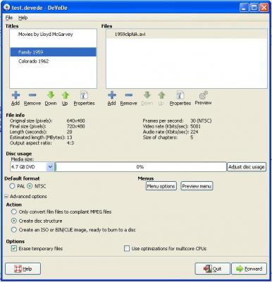
I use DeVeDe to create the files that go on the DVD. It converts my HuffYuv encoded AVI files to VOB files, which are actually MPEG2 format. In addition, it creates IFO and BUP files which complete the structure of a video DVD. These files can be verified on the computer – played like a normal DVD – before burning to the disc.

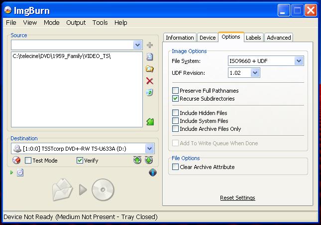
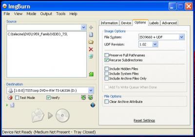
For burning DVDs, I use ImgBurn, another good freeware tool. Apparently, you have to know what you’re doing to create a DVD that works correctly in a normal DVD player. I don’t know what I’m doing, and with the Roxio software that came on my computer, the DVD would play, but skipped large portions of the movie. ImgBurn knows what it’s doing and makes good DVDs with the default settings. Once the movies are converted to VOBs, it only takes a few minutes to burn a DVD, so it’s easy to make multiple copies.

scr_imgburn.jpg

All DVD media is not created equal. Some of it is worthless, some is excellent, and some is in between. See this site for recommendations… digitalFAQ.


Tuesday, January 20, 2009

Trial Run

This is the first sample of a real movie captured with my machine. Some work to be done yet, but it proves the concept.
By including the sprocket holes in this test, I can see how much frame jitter is due to my projector and how much to the camera that made the movie. The main problem visible in this clip is the very non-uniform illumination – the diffuser is just a piece of crumpled paper in front of the LEDs. And the movie looks a little dirty, maybe that’s because I’ve been letting it roll out on the floor!
I have no idea who these people are – they came with the projector from Ebay.

ERROR: FLV player could not be loaded.

And here’s one of the first frames Dad ever shot. That’s my Mom (with me inside) and my sister in the Spring of ’58.

1959_easter.jpg

Here’s that same movie live, now using the opal glass diffuser…

ERROR: FLV player could not be loaded.

And finally, the AviSynth processed version…

ERROR: FLV player could not be loaded.

Oh yes – one more thing – here’s that clip from the VHS tape Dad had transferred professionally a few years ago. I watch it whenever I wonder if it’s really worth all this trouble…

ERROR: FLV player could not be loaded.


Monday, January 19, 2009

Clean Room

frm_dirt.jpgOnce the machine was getting nice captures, I started to pay attention to dirt on the film. Dad’s movies are in pretty good condition – they were always stored in metal cans and we were careful when projecting them – but the air is full of dust and there is just no way to keep it from hopping on to the film. This frame was not doctored in Paint – that’s genuine lint and I didn’t put it there on purpose! I’m using a DeSpot software filter in AviSynth to clean up the captured frames, and it works well, but it can’t remove everything without messing up real image. So the first line of defense is to clean the film and keep it clean while doing the telecine transfer.

I built a clean booth, a cheap substitute for the fancy laminar flow hoods that are used in laboratories and factories to keep dust particles out of precision equipment during assembly. The idea is to blow clean air down across the work area and out the door, carrying dust and lint away from the film. I mounted some editing rewinds to the side of the booth to use when cleaning the film. The supply reel goes on top. Cleaning is done in two passes; in the second pass, the film is wound upward back onto the supply reel, and dust is wiped off and down. The supply reel is then transferred to the telecine spindle, all at the top of the booth where the filtered air is entering.

100_0660.JPG

Four computer fans in the top box blow air straight down through a “dust and pollen” furnace filter. An “allergen” filter or HEPA filter is not necessary for this job, since particles smaller than 10 microns would never be visible to the camera anyway. The biggest culprits are the biggest airborne particles, mostly lint from clothing and carpets. Finer filters also restrict the flow more, and we want the most breeze to sweep dust out of the booth.

The booth has solved the dust problem completely. Now I might see visible bits of lint on 2 or 3 frames out of a 400′ reel, and the old problem of fibers that get caught in the projector gate and have to be removed is eliminated. The DeSpot filter and temporal degraining done in AviSynth handle whatever smaller particles remain, resulting in an amazingly clean final video.

After transferring a few hours of film, and living with this cabinet in the bedroom for several months, I realized what a monstrosity it was and decided to make a leaner one. The old cabinet is too big and heavy to move around, or even to easily set in a corner when not in use. Cleaning film while reaching up inside the door to turn the rewinds is pretty awkward. And the big plywood box is just plain ugly.

So, enter the less-is-more clean cabinet…

100_2285.JPG

With all acrylic sides, there’s more light inside, it’s easier to see what I’m doing, and it looks a lot neater. The box is less than half the size of the old one, and so much lighter that I can carry the cabinet with the telecine in it with one hand by the handle on top. So it’s easy to put it away when I’m done. The door slides open vertically and is held at any position by a little eccentric rubber tire at the side. And now the door can be closed completely to keep dust out when the fans aren’t running. The filter is a cut-to-size air conditioner filter supported by a piece of suspended ceiling eggcrate light diffuser.

This time, I mounted the rewinds in the side wall, so the cranking hand is outside and comfortable, and I’m facing the film and can inspect it more easily…

100_2280.JPG


Friday, January 16, 2009

Sample Frames

Here are some sample frames from my first full reel transfer of the 1959 Family movie, complete with the AviSynth post processing magic I learned from Fred Van De Putte. See a before and after comparison clip here… AviSynth clip.

Click images to see full resolution…

1959_garden.jpg

My sister lights my first birthday candle…

1959_bday.jpg

1959_playpen.jpg

The Memorial Day parade…

1959_parade1.jpg

My brother, the admiral…

1959_admiral.jpg

1959_boat.jpg

That’s Mom pulling out in a ’57 Ford Fairlane…

1959_car.jpg

I wish we had sound…

1959_trombone.jpg

My sister and her friend Janet have a sleepover. Well, there probably wasn’t much sleeping…

1959_girls.jpg

Badly underexposed available light. We never saw the girl in the shadows on the projection screen…

1959_play.jpg

Nor did we see my grandfather’s face in this shot…

1959_porch.jpg


Tuesday, January 13, 2009

Workflow

100_0592.JPG

Here’s my transfer procedure…

1) Turn on the clean booth fans, put the machine, film and cleaning stuff in the booth. Connect power and turn on the LEDs. Connect camera USB to computer. Blow out projector gate with Dust-Off.

2) Start TelecineApp.

3) Clean the film in the booth.

4) Load film on machine and run to start of first scene.

5) Setup for first scene…

Brightness: 64. This is the luma gain applied after all the other processing in the webcam chip. 64 represents a gain of 1 and I normally leave it there, since it can’t do anything useful that the post processing can’t do.

Saturation: -20. This controls the chroma gain at the end of the process chain. After all the other adjustments, I may tweak this to taste.

Gamma: 31. Normally, I have gamma all the way up, but a few scenes have a smaller range (the histogram spread is narrow) and reducing the gamma will take advantage of the extra range available and make the scene snappier.

White balance: After exposure is set pretty well, I turn on Auto WB until it settles, then turn it off and fine tune. The Philips Auto WB is pretty good, but the result is usually a little cool for my taste, so I usually turn the blue down a bit to warm it up.

Gain: 0. Gain is applied to the analog signal from the CCD, before the A/D converter. So it’s good for maximizing use of the 8 bit range when the shutter speed is not ideal.

Shutter: Start at 1/250 and increase exposure until the highest histogram is almost (but not quite) at the top. Use a little gain if the best shutter speed leaves more than about 15% of the range unused at the top. NEVER OVEREXPOSE! The movie will look a bit dark and dull and soft during capture. Don’t be tempted to brighten or sharpen it at this point. The post process will work magic on it, but only if it’s not overexposed!

Some scenes shot with available light are severely underexposed. These are basically black when projected, but can really be brought to life by the webcam. They’ll be very grainy and the color fidelity is poor, but it’s great to recover faces and details we thought were lost forever for want of those big, bright movie lights.

6) Start recording. Monitor movie on computer. Stop on Scene will stop the transfer when the scene exposure changes enough to require readjustment. Fine adjust gain during the transfer, but generally don’t touch any other settings until the scene change. When auto stop occurs, repeat step 5 and 6 for the next scene. Clips are saved as sequentially numbered AVI files. A 400 foot (30 minute) film might have 100-200 scene changes, and thus produce that many AVI files.

At the stop, I can do an instant replay with the built in player in TelecineApp. If I don’t like how something turned out, I can decrement the file number and redo it right then. If I’m not sure whether a little more exposure is better or not, I will “bracket” by running the scene twice and deleting the one I don’t prefer after post process.

7) At end of movie, use VirtualDub to delete the 2 or 3 frames at the clip changes where exposure settings were adjusted, as well as splice frames and any other garbage frames. To open the collection of files for edit, use “Open video file” for the first clip, then “Append AVI segment” to load all the subsequent clips at once. Then edit as one large movie and “Save as Segmented AVI” in “Direct Stream Copy” mode (copies original lossless compressed data without recompression). Segmented files are split into 2GB chunks, so I can archive on a FAT format external drive. This set of files is the master original, and represents the most hours of work, so it is carefully backed up. I can reprocess it as often as I like in the next step.

8) Post process with AVISynth in VirtualDub. Use Batcher to create scripts and launch VirtualDub with a command line listing all the scripts and output file names. VirtualDub SAVES the processed movie as a segmented AVI, again with HuffYuv lossless compression. I’m not keeping backups of the processed AVI, since I have the original edited transfer version, and in the future I’ll probably have a better script anyway.

9) Make DVDs with DeVeDe.

It takes time to do top quality telecine transfers. I’m spending 3 or 4 hours to scan a 400 foot reel. 2/3 of that time the machine is stopped and I’m adjusting settings for the next scene. After that, post edit takes another hour. Then I run the post process script, which requires about 4 hours to run on my laptop. This step doesn’t require any attention, but it is great to sit and watch the beautifully restored frames appear!

Here’s the system in action…

ERROR: FLV player could not be loaded.


Saturday, January 10, 2009

Talkies

Only two of Dad’s movies have sound tracks. Not lip-sync, record-in-the-camera type sound, but sound tracks added after the film was processed and edited. To do it, Dad sent the edited films back to Kodak and had a tiny magnetic stripe applied to the edge of the film. Then, using a Kodak Sound 8 projector borrowed from work, he recorded, or “dubbed” the sound onto the movie, like this…

img_sound8.jpg
Actually, the girl in that picture is probably recording more projector noise than voice!

In 1963, Dad spent two weeks in Rome on a business trip. It was the trip of a lifetime (at least at that point in his lifetime!) and warranted some special film making. Dad made a wonderful 30 minute movie and added classic travelogue narration including a few examples of his dry wit…

ERROR: FLV player could not be loaded.

Transferring a sound movie like this takes a little more work. My telecine machine has no provision for sound playback, so that had to be done separately. I did a little work on Dad’s newer Eumig projector and used it to copy the sound track to an audio cassette. Then I made an MP3 from the cassette using a freeware program called Audiograbber, though there are many options for this job.

Once the sound track and the movie were in digital form by their separate and devious paths, their lengths no longer matched. I used Virtual Dub to change the frame rate of the movie to 30 fps (by duplicating frames in a regular pattern), then modified the length of the sound track in the Audacity audio editor, using it’s “Change tempo” feature. I also applied a band pass filter (Equalization) to cut the hum and hiss from the recording.

With the AVI movie and the MP3 audio now the same length, I merged them in Virtual Dub and checked the sync. Some of the bits of narration were a few seconds early or late, so I used Audacity to shift them to the right place. Fortunately, Dad left long pauses in his narration, so it was easy to correct the timing by cutting the needed seconds of dead space and pasting it on the other side of the sound bite. I could imagine the patience it took him 45 years ago to get the timing right as he watched the film and read into the mic from his script.

The Rome movie was always one of our favorites, and the digital version is even better.

Some more samples…

ERROR: FLV player could not be loaded.


ERROR: FLV player could not be loaded.


ERROR: FLV player could not be loaded.


Saturday, January 3, 2009

Dynamic Range

dwg_k40curves.jpgNow, a few words about the number one problem in movie scanning. It’s clearly evident in this plot. Well, maybe it’s not that clear. Let me explain.
The plot shows the density on the processed film as a function of the exposure. These curves are the most important characteristic to be understood about any particular film, so they are called the “Characteristic Curves”. Density is the log of % of light blocked by the developed image, in this case, by the dye layers of the Kodachrome 40 movie film. Plotted against LogE, or log exposure – the amount of light striking the film when it is exposed in the camera.

Kodachrome is a reversal film, meaning that after it is developed, it is not a negative, as with “print” film, but the image looks just like the scene that was photographed, and you can view it with a projector directly, rather than making prints from the negative.
If the slope of the main part of those curves was -1, then a LogE change of exposure of 1 would result in a change in density of -1, and the image on the film would have the same dynamic range, or apparent contrast, as the scene.

But with most reversal film, the slope is steeper than that, meaning the contrast of the final image is greater than that of the scene. “Kodachrome, They give us those nice, bright colors…”
This is great for 8mm movies, which are usually viewed in a half darkened room with a cheap projector using a not-too-bright lamp and a lens with lots of flare. The high contrast of the image compensates for the bad viewing conditions.

But this feature is a big problem for scanning the film, as we are trying to do in a telecine machine. The dynamic range – the ratio of the lightest to the darkest parts of the scene – is quite a bit wider on the film than in the actual scene, meaning we really need a better digital camera to scan the film than we would need to capture the scene in real life. A density change of 1 is equivalent to about 3 photographic stops, or about 3 bits of digital data. As you can see in our plot, Kodachrome 40 is capable of a dynamic range of 3 to 3.5 in density, which means we really need a camera capable of at least 10 bits per pixel to record it all accurately.

Consumer quality cameras are typically limited to about 8 bits of dynamic range. The webcam I am using actually has a 10 bit A/D converter, but as with most tiny CCD imagers, the 2 least significant bits of data are mostly noise. We need bigger pixels and a good analog signal path to get 10 bits or better, and that means a lot more expensive camera.

There are a few things to do to make the most of the 8 bit data. A nicely diffuse light source, balancing the illuminant to match the CCD response, and minimizing flare and light leaks in the optics, and carefully adjusting exposure and gamma are all critical. As I said earlier, the most important rule is DON’T OVEREXPOSE. In the sample frames above, there are shadow areas that appear completely black, but if you examined the film under a microscope, you’d see lots of detail in those shadows – folds of fabric, leaves of trees, blades of grass – but it’s all gone black in my frames. Yet the frames look pretty nice, because the highlights are not clipped. Our eyes and/or brains are usually a lot more focused on the highlights, and when they are “blown out” or clipped, the image looks really bad. So we almost always expose for the highlights. Plus, in digital imaging, highlights that are just a bit overexposed are clipped quite abruptly to white, whereas the shadows smoothly disappear into the noisy blackness. Occasionally, there is something really important in those shadows – a face, for instance – and we might want to compromise the whole scene just to see that face. But most of the time, we want to preserve the highlights to make the film look great. Then it’s only if you compare the digital side by side with the film that you’ll see what’s missing.

So I can’t capture the true dynamic range of the film, but the webcam actually does a pretty good job. If you examine a film frame under a microscope, you can see that the digital capture does not have the same tonal range. On the other hand, the digital rendition looks great compared to the way we used to watch the movies with the old DeJUR projector, and it’s far, far better than the VHS tape Dad paid $100 for a few years ago. I wouldn’t use my webcam based machine for archiving priceless museum film, but it will certainly make my family happy.


Friday, January 2, 2009

Nanometers

I first planned to use white LEDs to illuminate the film. But now I think the ideal source is an RGB LED. Here’s why…
White LEDs are actually blue LEDs with a patch of phosphor inserted that absorbs some of the blue light and re-emits green-red light to produce a visible white color. The resulting spectral distribution of this source looks like this:

dwg_ledwhite.jpg
In a telecine machine, we are trying to measure the density of 3 layers of colored dyes in the processed film. For Kodachrome movie film, the spectral densities of these dyes look like this:
dwg_k25density.jpg
The CCD imager that I am using to measure the density of these dyes has a color filter array (CFA) made of colored dyes. The spectral transmittance of these dyes, combined with the spectral sensitivity of the silicon sensor, results in a sensitivity of the device that looks like this:

dwg_ccdspectral.jpg

The peak response wavelengths of the red, green and blue pixels in the CCD almost match the peak blocking wavelengths of the red, green and blue dyes in the film as shown above, making the CCD a fine device for measuring the color on the film. The white LED spectrum doesn’t match so well, but look at the spectral output of the RGB LED…

dwg_ledrgb.jpg
Now we have a narrow band illuminant that matches the film dyes and the CCD pixels very nicely (though it would be nice to have a bluer blue). Aside from the obvious elegance on paper, this allows the illuminant intensity to be adjusted so that the red, green and blue pixels of the CCD will all saturate at the same exposure setting. Or, more important, it means that an exposure setting can be chosen that will nearly saturate all three colors, meaning we are using the full dynamic range of the CCD, which is, after all, somewhat limited.


Thursday, January 1, 2009

Dollars

I said that this machine cost less than $200, but that’s not completely true. The cost of the parts I had to buy that I actually used was around $180. I already had the motor and a lot of other small parts that might total another $30 or $40 to buy.

I spent $150 or so on things I didn’t end up using – the Logitech webcam, the AC motor speed control, white LEDs, etc. That’s the cost of engineering, but it doesn’t count as the “direct cost” of the finished machine. The items are still usable or salable.

Last, but certainly not least, is the lens. I’ve not seen a 17.5mm Baltar for sale on Ebay or anywhere else, so I don’t know what it would cost. If I didn’t have that lens, I would shop for a similar 8mm or 16mm movie camera lens. I tried a cheap Chinese 16mm CCTV lens, but it was not very good.